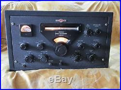
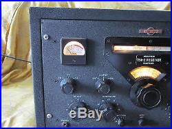
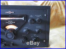
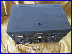
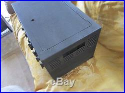
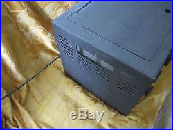
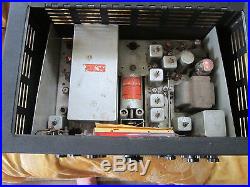
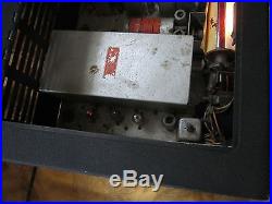
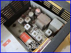
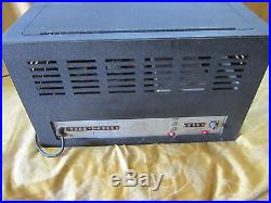
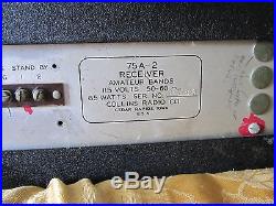
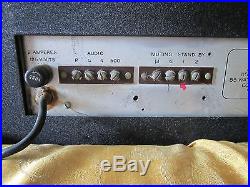
This is info I found about this unit from another website. This equipment was inherited from the estate of a dear friend. He was an engineer and an avid Ham radio operator and servicer. He repaired lots of equipment and I do have all of his testing equipment. This unit was hooked up in his shop he had a total of 6 units hooked up in his system. I assume it may work as it was with the others. I tried to contact some local Ham operators and they never came out to look at them nor help me in anyway so they are up for sale ASIS parts. If its not in the pictures it’s not included. Voltage: 115V, 50-60 85W. FREQUENCY COVERAGE – The amateur bands are covered as follows. 160 meters – 1.5 – 2.5 mc 15 meters – 20.8 – 21.8 mc. 80 meters – 3.2 – 4.2 mc 11 meters – 26.0 – 28.0 mc. 40 meters – 6.8 – 7.8 mc 10 meters – 28.0 – 30.0 mc. 20 meters -14.0 -15.0 mc. BANDSPREAD – The permeability tuning system employed in the 75A has been engineered to give linear tuning on each band. Ten turns of the vernier tuning dial cover each of the individual ranges shown above. Each division of the vernier tuning dial (which has 100 divisions) represents 1 kc on the 160, 80, 40, 20, and 15 meter bands, and 2 kc on the 11 and 10 meter bands. ACCURACY AND STABILITY – Visual tuning accuracy to within 1 kc from 1.5 mc to 21.8 mc and 2 kc from 26 mc to 30 mc provided the vernier dial corrector (zero set control) is exactly calibrated at the centers of each tuning range. Extreme variation in plate supply voltage causes a change of only a few cycles in the CW note. Furthermore, the CW note is absolutely independent of all except the tuning controls Physical shock will not disturb the frequency unless the shock is severe enough to change the dial settings. The stability is available after a very short warm up. IMAGE AND I-F REJECTION – The circuit design of the 75A receiver has inherently high rejection to spurious frequencies. Image rejection is a minimum of 50 db. I-F rejection is 50 db minimum. SENSITIVITY AND SIGNAL TO NOISE RATIO – A 10 db signal to noise ratio and one watt of audio output is obtained with signal inputs of 2 microvolts or less. SELECTIVITY – The crystal filter controls provide a bandwidth that is variable ln 5 steps from approximately 4 kc to 200 cycles at 2 times down (6 db down from the peak of the resonant frequency). There is only slight loss in gain caused by use of the crystal filter with the exception of the extremely sharp position which gives about 6 db loss. The fixed I-F selectivity provides a bandwidth of approximately 13 kc at 1000 times down (60 db down from the peak of the resonant frequency). PHASING – The crystal filter includes a phasing control which provides a rejection notch for suppressing heterodynes. The range of rejection of this control has been extended downward to 250 cps or lower. AUTOMATIC NOISE LIMITER – The 75A receiver contains a series type noise limiter which automatically adjusts its limiting threshold to all carrier levels. CW NOISE LIMITER – A shunt type noise limiter with front panel control of limiting level is provided for CW operation. AUTOMATIC VOLUME CONTROL – Delayed, amplified AVC gives constant output within 6 db for a change in r-f input from 5 microvolts to 0.5 volt. AVC is applied to the r-f stages and three i-f stages. The proper amount of AVC delay is employed for maximum sensitivity on weak signals. SIGNAL STRENGTH METER – The S meter is calibrated from 1 to 9 in steps of approximately 6 db each, and for 20, 40, and 60 db above S9. Zero adjustment is provided. A reading of S9 is obtained with an input of approximately 100 microvolts. The AVC amplifier tube works into an unusually low value of load impedance which permits quick recovery from noise pulses or strong signals from the associated transmitter, thus allowing. Fast break-in when the receiver is used to monitor operation of the transmitter. AUDIO OUTPUT – 2.5 watts of audio power are available. Thank you for looking. The item “Vintage Collins 75A-2 1500 kc 30 mc CW MCW AM PHONE Tube Ham Radio Receiver” is in sale since Sunday, August 02, 2015. This item is in the category “Consumer Electronics\Radio Communication\Ham, Amateur Radio\Ham Radio Transmitters”. The seller is “mark31632″ and is located in Hahira, Georgia. This item can be shipped to United States, to Canada, to United Kingdom, DK, RO, SK, BG, CZ, FI, HU, LV, LT, MT, EE, to Australia, GR, PT, CY, SI, to Japan, to China, SE, KR, ID, to Taiwan, to Belgium, to France, to Hong Kong, to Ireland, to Netherlands, PL, to Spain, to Italy, to Germany, to Austria, RU, IL, to Switzerland, NO, SA, AE, QA, KW, BH, HR.
- Brand: Collins
- Supported Modes: CW