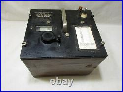
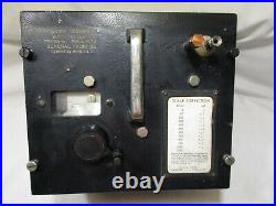

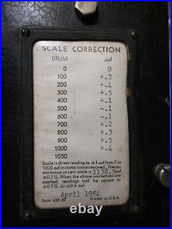

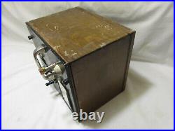


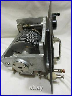
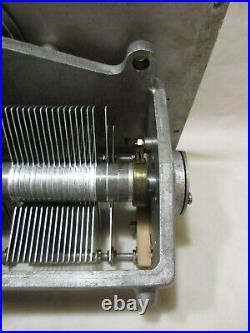
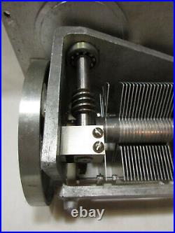
For sale is a vintage GENERAL RADIO Precision Condenser, Model 722-M, made prior to 1939. It was left in the electronics test equipment inventory of my late father, who was HAM radio operator for 73 years, was an Army Signal Corps Radio School instructor during the War, and was a radio and other electronics serviceman for much of his life. He loved radio and working on them! My husband did quite a bit of research to tell you about this unit. This is some of what he has found. Description : This General Radio Co. Type 722-M variable air condenser (or air-dialectric capacitor) was designed to be a precise, stable capacitance standard. It is a rare, vintage, pre-War table model instrument, with four rubber feet, mounted on a sturdy aluminum panel, finished in black crackle lacquer. The condenser is housed in a finished walnut cabinet, which is lined inside with a copper Faraday Shield, to protect the condenser from external electromagnetic fields. The scale was designed for direct reading from zero to 1000 micromicrofarads (picofarads) in capacitance REMOVED. So, as the scale moves from 0 to 1,000, the capacitance of the precision condenser is being continually reduced. The scale is graduated in micromicrofarads (picofarads). This instrument can be seen in General Radio Company Catalog “J, ” dated September, 1936, page 30, available on the internet. Catalog “K, ” dated 1939, page 45, depicts a revised Type 722, with the addition of a third terminal. Type Number : 722-M Serial Number : 715. Year of Manufacture : Prior to 1939. This device has a calibration certificate dated April, 1954. That is only the calibration date–not necessarily the date of manufacture. 1954 vintage Type 722 condensers had three terminals, not two! Category : Accurate, precision Capacity Standard. The design, full-scale change in capacitance of this instrument is 1,000 micromicrofarads. A micromicrofarad is an obsolete unit of capacitance, which is the present day equivalent of the picofarad. Application : Used as a standard in alternating current a. Bridge circuits, or held as an external capacitance standard for substitution measurements in a. This precision variable, air-dielectric capacitor was designed for application wherever stability and accuracy are critical. The Type 722 has been used as a tuning condenser in conjunction with oscillators, frequency meters and other instrumentation. Construction : The plates of this condenser are made of aluminum. Aluminum alloys were used in the manufacture of the condenser frame, rotor shaft, stator rods, and spacers. The selection of aluminum and its alloys was designed to minimize the weight of the unit and to optimize the temperature coefficient of capacitance, providing uniform linear expansion of these components, while simultaneously furnishing mechanical strength similar to brass. The condenser assembly is secured in the rigid, cast frame. The worm gear, which drives the condenser, is machined into the worm driveshaft to minimize eccentric deviations and backlash. The crank-type dial end of the worm-drive is mounted in a ball bearing. The opposite end of the worm drive is supported by an adjustable spring mounting. Both ends of the rotor assembly shaft are also mounted in ball bearings. To facilitate superior, reliable, electrical connection to the rotor, a brass drum is incorporated into the rotor assembly, and dynamically wiped by a phosphor-bronze brush. The stator assembly is supported by two bars of solid, low-loss, dielectric (Isolantite). The entire condenser assembly is mounted on a sturdy aluminum panel, and housed in a finished, shielded walnut cabinet, with four rubber protective feet. One of the terminals is connected to a copper Faraday Shield, which lines the cabinet interior to protect the condenser from external electromagnetic fields. A conical, dielectric bushing insulates the other terminal from this shield. Calibration : This Type 722-M was calibrated in April, 1954. The Calibration Certificate is protected by a clear plastic sheet in a brass frame, and fastened to the black, lacquered, aluminum panel. Accuracy & Reliability : The precision of setting was designed to be one part in 25,000 of full scale. Direct-reading accuracy was designed to be within +/- 0.1% of the full scale i. The calibration certificate mounted on the instrument panel was intended to achieve similar direct-reading accuracy for settings below full scale. Corrections (to the nearest 0.1 picofarad) were recorded for 100 picofarad sale intervals. The actual zero-scale capacitance of this device, at the time of calibration (April, 1954), was recorded on the certificate as 1,138 picofarads. The plates of the condenser were designed to be semi-circular, thereby producing a linear capacitor characteristic. By design, there is no calibration error due to backlash IF desired settings are approached in the direction of increasing scale reading i. Temperature Coefficient of Capacitance : By design, the Type 722-M had a temperature coefficient of capacitance of approximately +0.002% per degree Centigrade for small changes in temperature. Style : Table model with a sturdy panel-mounted handle for portability. This Type 722-M precision condenser has four rubber, protective feet for surface protection of lab counters or table tops. Guidance : The condenser is mounted on a sturdy aluminum panel, which is secured to the walnut cabinet by four (4) #10-32 machine screws. Removing the four screws permits the panel and the attached condenser assembly to be lifted out of the cabinet. Cabinet : The finished cabinet is made of walnut. Faraday Shield : The walnut cabinet is lined with a copper Faraday Shield to protect the condenser from external electromagnetic fields. The shield is connected to the aluminum panel and the rotor terminal. Panel : The aluminum panel is the mounting base for the condenser, which is secured to its underside. The panel is finished in black, crackle lacquer and features the viewing window for the scales, the crank-type dial which operated the condenser, scales, etc. , a handy, sturdy handle for portability, a mounted calibration certificate, and two terminal binding posts. Terminals : The terminal binding posts are on 3/4 centers. The rotor terminal has a jack-top binding post, which is connected to the panel and the Faraday Shield. A conical dielectric bushing insulates the other terminal from the shield and aluminum panel. Maximum Voltage : Maximum voltage applied to this device must not exceed 1,000 volts, peak. Scales : The scales are viewed through a window (about 1-inch by 2-inch) which permits the user to read the master scale (which rotates in a vertical plane), and also the fine tuning scale (which rotates in a horizontal plane). The master scale is graduated in increments of 50 picofarads over the full scale, from 0 to 1,000. The fine-tuning scale is graduated in picofarads from 0 to 50. A crank-type dial operates both scales, rotating counter-clockwise 20 complete turns as the full scale is traversed from 0 to 1,000 picofarads. Nominal Dimensions : About 8″ by 9-1/8″. It is 8-1/8 high (over the carrying handle and the rubber protective feet). Public or private museums, University or private labs, collectors of General Radio Co. Equipment, collectors of pre-War test or lab equipment, science teachers, scientists, etc. An awesome display and conversation item! Thanks for reading all about this piece of equipment!! I hope it is one that you would love to add to your collection! Thanks for looking here! This item is in the category “Collectibles\Radio, Phonograph, TV, Phone\Radios\Tube Radios\1930-49″. The seller is “churrolady” and is located in this country: US. This item can be shipped to United States, Canada, Bahamas.
- Modified Item: Yes
- Country/Region of Manufacture: United States
- Modification Description: Item will most likely need to be recalibrated.
- Brand: General Radio
- Time Period Manufactured: 1930-49